

Welcome to our deep dive into the fascinating world of hydraulic turbines and hydroelectric power generation! You may wonder how the energy of rushing or falling water becomes the electricity that lights up our homes and powers our devices. It’s a remarkable transformation that happens in hydroelectric power plants, thanks to an ingenious piece of engineering known as the hydraulic turbine. In this blog, we’ll unravel the features, workings, and implications of these turbines in a manner that’s easy to understand yet packed with information. So, strap in for an engaging journey through the life force of our modern world – hydroelectric power!
At the core of hydroelectric power generation are hydraulic turbines. But what exactly are they? A hydraulic turbine is a type of turbine that harnesses the kinetic and potential energy of water to generate mechanical energy. This energy then drives a generator, which converts it into electrical energy. In essence, the entire process revolves around transforming the energy inherent in water flow into usable electricity. The hydraulic turbine sits at the heart of this transformation, acting as the crucial intermediary between water energy and electrical power. We’ll delve deeper into its inner workings in the sections to follow. As complex as this might sound, it’s essentially a testament to human ingenuity in leveraging natural resources for our needs.
To state it in a simple way, turbines are machines that convert some form of energy into mechanical energy. Based on the working medium used we have steam turbines, hydraulic turbines and gas turbines. Of these hydraulic turbines are those turbines which convert hydraulic energy (energy possessed by water) to mechanical energy. Mechanical energy is produced in the form of a rotating shaft. Hydraulic turbines are one of the older but still used mechanical devices for power extraction. Read on to know more about how hydraulic turbines play a role in hydroelectric power generation.
Brief History
The development of hydraulic turbines spreads across centuries. Primitive forms of these were used since medieval times and even during the time of the Roman Empire. Simple water wheels were the first to be developed. Water wheels served as the basis of the modern hydro turbines. In water wheels the energy possessed by flowing water was used to turn a large wheel fitted with several buckets. Ever since the development of water wheels the development of hydro machines was very slow. The Romans invented two helix mills, which were used to grind grains in mills. Various new turbines were later on developed, but all of them had practical difficulties and reduced efficiencies.
Finally, it was in the year 1849 that James B Francis came up with a much more efficient and improved version of hydraulic turbine. The turbine was named after him, and thus the Francis turbine came into operation. Further research works on hydraulic turbines concentrated upon extracting the energy possessed by a water jet. This eventually led to the development of the impulse turbine by Lester Pelton in 1879 which later on came to be known as Pelton Wheel. Various other turbines were developed during the following years. Francis turbine and Pelton Wheel are still widely in use.
Power Generation Using Hydraulic Turbines

All hydraulic turbines require water from a reservoir or lake at a considerable height for their working. This
is obtained by either construction dams/reservoirs or by taking water from a lake on a mountain. Dams are the most common way for generating hydropower. The basic layout of a hydroelectric dam is shown here. Water is maintained at a great height in the reservoir. For beginners we can simply call this height as the head of water available for a turbine. Higher the head of water available, higher is the energy available from water. Water from the reservoir is carried through large diameter pipes called penstock. This water under pressure is fed to the turbine. The energy possessed by water is then used to turn the turbine shaft. The turbine shaft is coupled to an electric generator. As the shaft rotates, electricity is generated by the generator which is then fed to the power grid. The water leaves the turbine and is expelled onto a tail race.
Basic Parts of a Hydraulic Turbine

Although various forms of turbines are there, all turbines essentially consist of the following parts:
Vanes
The vanes of a hydraulic turbine, also known as blades or buckets, are fundamental to its operation. They are carefully designed and oriented fixtures that interact directly with the flowing water. As water strikes these vanes, the kinetic and potential energy of the water is transferred to the turbine, causing it to spin. The number, size, shape, and configuration of the vanes are all meticulously designed based on the specific requirements of the hydroelectric plant, such as the volume and speed of water flow, and the desired electrical output. In essence, the vanes are the point of energy transfer from water to the turbine, setting the stage for the subsequent conversion of mechanical energy into electrical energy.
Shaft
The casing is the third essential part of a hydraulic turbine. It is a robust, hollow structure that houses the vanes, the shaft, and other elements of the turbine. The casing is carefully engineered to withstand the pressure of the water flowing through it while providing an efficient path for the water to strike the vanes. It also serves a protective role, shielding the internal components of the turbine from external elements and potential damage. Furthermore, the casing assists with water flow regulation, ensuring that the water hits the vanes at the optimum angle for maximum energy transfer. It is designed considering numerous variables like turbine size, type, and the specific hydraulic conditions under which it will operate. In summary, the casing is a vital component that contributes significantly to the overall effectiveness and longevity of a hydraulic turbine.
Casing
The casing is the third essential part of a hydraulic turbine. It is a robust, hollow structure that houses the vanes, the shaft, and other elements of the turbine. The casing is carefully engineered to withstand the pressure of the water flowing through it while providing an efficient path for the water to strike the vanes. It also serves a protective role, shielding the internal components of the turbine from external elements and potential damage. Furthermore, the casing assists with water flow regulation, ensuring that the water hits the vanes at the optimum angle for maximum energy transfer. It is designed considering numerous variables like turbine size, type, and the specific hydraulic conditions under which it will operate. In summary, the casing is a vital component that contributes significantly to the overall effectiveness and longevity of a hydraulic turbine.
Tailrace
The tailrace, or draft tube, is the final key component of a hydraulic turbine system. It is the conduit through which water is led away from the turbine after it has imparted its kinetic and potential energy to the turbine’s vanes. The design of the tailrace is critical as it directly influences the efficiency of the turbine. It is gracefully tapered to gradually reduce the velocity of the water, while simultaneously increasing its pressure before it is discharged back into the river or the sea. This process recovers some of the kinetic energy of the water, further increasing the overall efficiency of the turbine. Therefore, the tailrace plays a vital role in the hydraulic turbine by ensuring that the water used to generate power is safely and efficiently returned to its source.
Different Types of Energy in a Flowing Fluid
A fluid in motion generally has three kinds of energy associated with it. These are:
- Potential energy: Energy possessed by the fluid by virtue of its position (same as the energy possessed by a stone falling under gravity).
- Kinetic energy: Energy possessed by the fluid by virtue of its motion (just like a moving bullet has some energy associated with it).
- Pressure energy: Energy possessed by the fluid on account of its pressure.
Bernoulli’s equation governs the energy changes of a flowing fluid. This equation has very large applications and is familiar to all high school students. In simple a simple way Bernoulli’s equation states that the total energy of a flowing fluid is a constant. That is the sum of kinetic, potential and pressure energies of a flowing fluid is a constant.
Kinetic energy + Potential energy + Pressure energy = constant
Bernoulli’s theorem helps us in understanding energy changes during flow inside a turbine.
ALSO CHECK OUT OUR OTHER ARTICLES
Types of Hydraulic Turbines and Their Working
1. Impulse Turbine (Pelton Wheel):

Wikimedia Commons User:Markus_Schweiss

In impulse turbines, the kinetic energy of a high-velocity water jet is used to rotate the runner which in turn develops mechanical power. The basic construction consists of a large wheel around the periphery of which a number of buckets are attached. These buckets (which act as vanes in this case) are so shaped that the water jet gets deflected sideways when it hits them. Water from the penstock is passed through a nozzle which increases the velocity (and hence the kinetic energy) of water. This produces a high-energy water jet. This jet is directed tangentially at the wheel.
Usually in hydroelectric power stations, a number of jets are used around a runner.
2. Radial Flow Reaction Turbines

In reaction turbines such as Francis turbine, water under pressure is made to pass through the runner and create the turning effect. A reaction turbine consists of a scroll casing that is filled with water. The casing is scroll-shaped (that is its cross-section goes on reducing). Water at the inlet had both kinetic as well as pressure energy. As the water moves through the scroll casing, a part of the pressure energy continuously changes to kinetic energy. A special arrangement of guide vanes is fitted around the runner of the turbine. Water is guided onto the curved blades of the runner by means of these guide vanes. The swirling water moves the blades and creates a rotating effect on the runner. A shaft attached to the runner is coupled to the generator. For large turbines, the shaft is made vertical.
3. Axial Flow Reaction Turbines
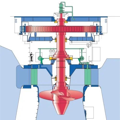
Wikimedia Commons User: Markus_Schweiss
In an axial-flow reaction turbine water flow is parallel to the axis of the turbine. The runner is shaped just like a propeller. Guide vanes direct water axially onto the runner from the scroll casing. As water flows through the runner its pressure energy goes on changing to kinetic energy(according to Bernoulli’s theorem). The best example of this turbine is the Kaplan turbine, named after the Austrian engineer V Kaplan. It’s most suited for large water flow under small heads. The blades on the runner (which is called a hub in this case) are adjustable so as to control the amount of water flowing through it.
Power generation from hydraulic turbines is by far one of the cleanest methods of power generation since it does not pollute water in any form. However, the construction of dams may lead to disruption of the nearby environment and obstruct natural river flows.
Conclusion
Hydraulic turbines continue to play a crucial role in generating hydroelectric power, a renewable energy source that harnesses the power of water to produce electricity. Each type of turbine, whether it’s an impulse turbine, reaction turbine, or axial flow reaction turbine, offers unique advantages depending on the conditions and requirements of the site. While the environmental impacts associated with dam construction cannot be overlooked, the long-term benefits of clean, sustainable power generation significantly contribute to our global efforts against climate change. It’s clear that hydroelectric power, powered by the humble hydraulic turbine, will remain an essential part of our energy mix for the foreseeable future.


